Helium leak test for fuel cell plates
Helium leak test for fuel cell plates
For the reliable testing of single and bipolar plates
Alternative to combustion engines
Electric drives will be dominating the automotive market in the coming years, while the number of vehicles with combustion engines will go down.
Hybrid and battery solutions will be the preferred option for passenger cars in the near future, but the use of fuel cell drives and the use of hydrogen as fuel will have a high significance as well. Particularly for heavy load transport, commercial vehicles, vessels, aircrafts and public transport fuel cell fuel cell drives are a real alternative. Short re-filling cycles and a sufficient operating range are the main advantages of this concept. If the hydrogen is produced with alternative energies (e.g. wind turbines or solar power), the ecological balance is positive (“green hydrogen”).
The fuel cell
A fuel cell mainly consists of an anode, a cathode and in between layers of so called “bipolar plates”, which are separated by a membrane (gas diffusion layer).
On one side hydrogen gas is supplied to the fuel cell and on the other side oxygen (air). The positively loaded particles of the hydrogen pass the gas membrane, while the negatively loaded electrons cannot pass. As electric quantities always endeavour to balance the loading, the negatively loaded electrons stream along the outer connections to the other side of the fuel cell.
This electric current can be used to run an electric drive or charge a battery.
The hydrogen ions unite with the supplied oxygen to water or steam which leave the process as exhaust.
Helium leak test for testing of bipolar plates
A main part of the fuel cell are the bipolar plates. It is very important for the process that the bipolar plates are leak free and no gas can pass the intended process because of leakages. We have developed a helium leak test to check the plates.
This device is able – with the specific tooling – to test single plates as well as bipolar plates. During the test cycle the different circuits are leak tested against each other:
- water circuit to the outside
- water circuit to the hydrogen circuit and to the oxygen circuit
- Hydrogen circuit to the oxygen circuit
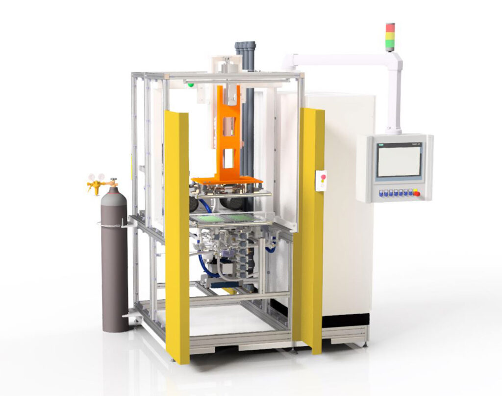
Main module for manual handling
The main module can be extended with more (sub-) modules if the production demands require it. With the smallest setup 150 parts per hour can be tested, with the largest setup and automation level 700 parts per hour can be tested (400 parts per hour with manual handling).
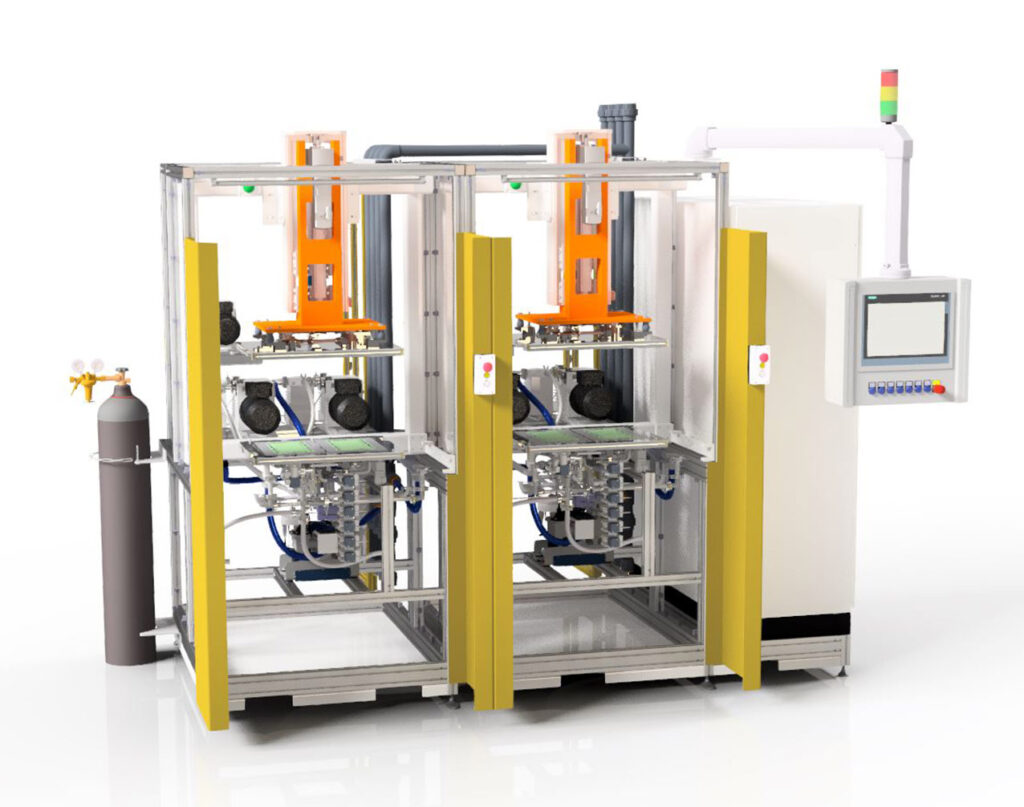
Main module and sub module for manual handling
Main module with two or more sub modules module for manual handling
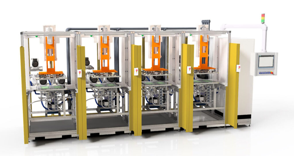
The following options are available as upgrades:
- Testing of end (cooler) and dummy plates
- Laser marking
- Transport systems to supply and discharge test parts
- Robot handling for loading and unloading of parts
- Vision system for location of the plates on a loading conveyor (as support of the robot handling)
- Reject station
- Rework station
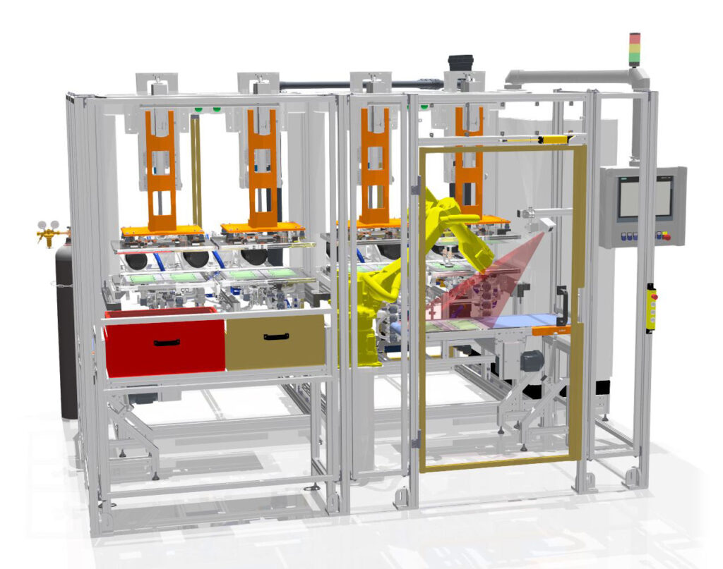
Full automation with robot handling (700pph)
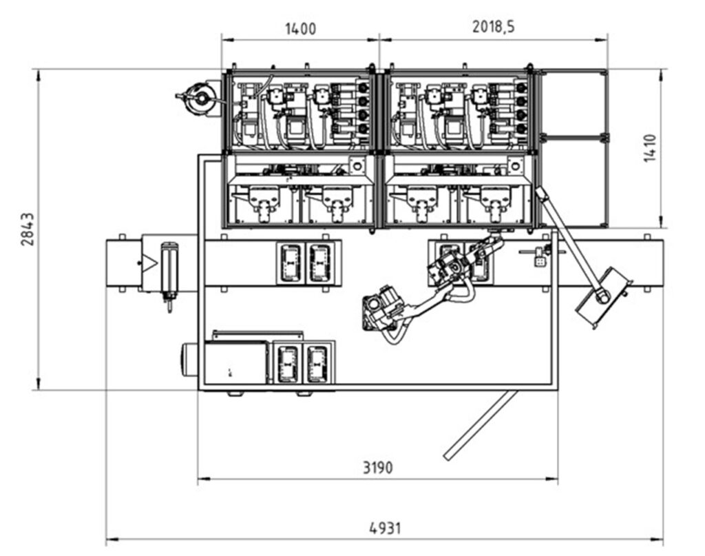
Floor space requirement
Fully automated part handling by robot
Manual part handling
Details of the helium leak test
The test parts are positioned in the lower half of the test chamber by using locator points and the parts are then fixed by a vacuum system. Each module tests two parts at a time. As soon as the parts are loaded and fixed, the chamber closes, and the helium leak test will be executed. After the test cycle the chamber opens and the tested parts can be taken out.
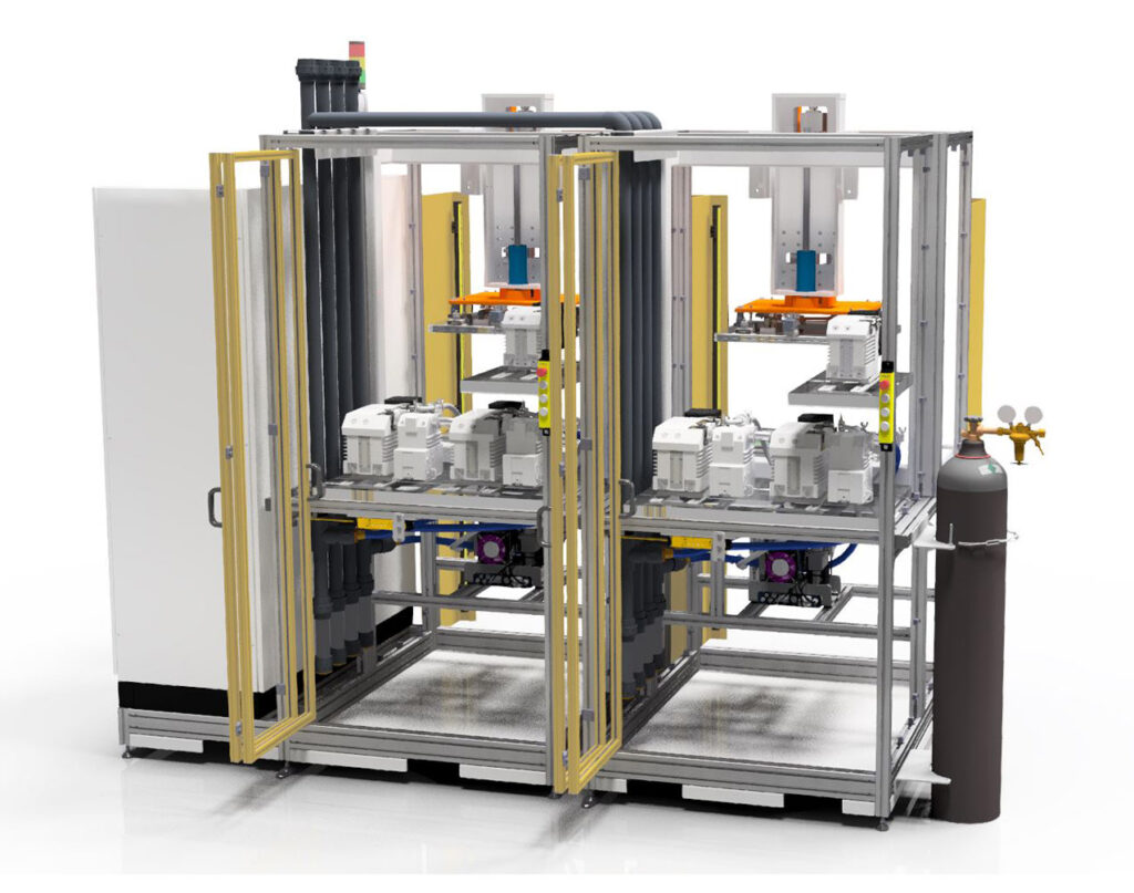
Set of pumps and mass spectrometer (two modules)
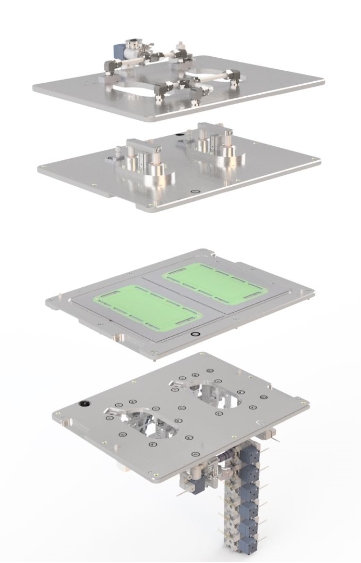
Setup of the test chamber and the exchangeable inserts
Each test chamber can be equipped with a separate set of pumps and a mass spectrometer.
Maintenance and tool change
The module is very well accessible for maintenance through the large service doors on the rear side. The tool change for the product specific parts in the test chamber has to be done from the operator side (front side). The tool change can be done by one person within a few minutes.
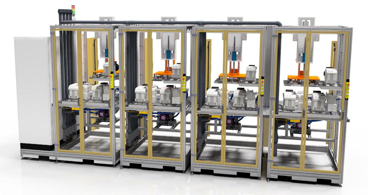
Rear side of a 4-module device with service doors
Contact us for more information

Daniel Schönbohm
Sales
Worthmann and MACEAS